


In low-latency trading, teams often obsess over shaving microseconds off a single RPC call—kernel bypass stacks, custom codecs, hand‑rolled gRPC pipelines.
Those optimizations matter, but they only describe a tiny slice of the real latency story. In production, your strategies live or die not by lab‑bench “RPC latency” alone, but by how your network and servers behave under heavy, bursty load.
Server bandwidth, link capacity, and how you design for microbursts and fan‑out determine whether you consistently see those microsecond RPC numbers—or end up paying a “congestion tax” on every trade.
Latency in trading: More than one number
From a capital markets perspective, latency is the time from “event” to “execution”: a market event occurs, the venue encodes it, data travels over networks, your application makes a decision, and an order travels back to the venue for matching and confirmation.
That total delay is built from multiple components:
| Component | Explanation | Dominant factors | Typical scale |
|---|---|---|---|
| Propagation | Bit travel time A→B | Distance, fiber vs RF | μs per km |
| Processing | Handling by devices/software | CPU/NIC/switch architecture, code path | ns–ms |
| Queueing | Waiting in buffers under congestion | Instantaneous load vs link capacity | 0–ms+ (spiky) |
| Serialization | Time to put bits on the wire | Message size, link bit-rate | sub-μs–ms |
Propagation is largely governed by physics (speed of light in fiber ≈ 4.9 µs/km), which is why colocation and microwave links matter.
But processing, queueing, and serialization are where server bandwidth and network design really show up. As message rates increase into the hundreds of thousands or millions per second, available throughput and queueing begin to dominate your actual latency distribution.
Microbursts, buffers, and why bandwidth headroom matters
One of the biggest traps in trading network design is relying on one‑second averages. In practice, market‑data flows are extremely “bursty.” Arista’s HFT solution brief describes a BATS exchange feed where:
- The one‑second average bandwidth is ~86 Mb/s;
- The 1 ms window can spike to ~382 Mb/s.
Viewed side by side:
| Metric window | Observed rate (Example) | Link capacity | Risk on 1 GbE | Risk on 10 GbE |
|---|---|---|---|---|
| 1 s average | 86 Mb/s | 1 Gb/s | Low | Negligible |
| 1 ms microburst | 382 Mb/s | 1 Gb/s | Queueing/loss | Very low |
On a 1 GbE link, a 382 Mb/s microburst is already a significant fraction of capacity in that instant. If multiple feeds or internal streams converge (fan‑in), you can easily oversubscribe the link for microseconds to milliseconds. The result:
- Queues grow in NICs and switches → packets wait in buffers → your effective latency jumps.
- Buffers overflow → packet drops → TCP retransmits (adding RTTs) or silent loss on UDP multicast.
On a 10 GbE link with the same traffic pattern, you have an order of magnitude more headroom. The burst doesn’t disappear—but it’s far less likely to create queueing or loss.
In other words, high bandwidth doesn’t magically accelerate each packet; it dramatically lowers the probability and severity of congestion, which is what ruins latency profiles during real events.
This is why serious trading networks focus on microburst behavior, buffer sizing, fan‑in/fan‑out patterns, and link utilization at sub‑millisecond granularity—not just average Mbps.
RPC is fast—Until the network isn’t
When engineers say “our RPC is fast,” they typically mean something like:
- Services are colocated in the same datacenter or region.
- The RPC stack uses kernel bypass or tuned TCP.
- Payloads are small, and the call path is hot in cache.
- Benchmarks are run under low load, often between just two nodes.
Those are valuable optimizations. But in an actual trading system, you’re dealing with:
- Inbound: multiple market‑data feeds, admin streams, drop copies, telemetry.
- Outbound: orders, cancels, and modifies from many strategies.
- East–west: pub/sub distribution to strategies, risk engines, monitors, and storage.
During a volatility spike, these flows can converge on specific NICs, top‑of‑rack (ToR) uplinks, or core switches. If a critical link runs near saturation, queues form and your RPC packets simply wait in line. The RPC implementation itself hasn’t changed; the environment around it has.
Data‑center research like HULL (“Highbandwidth Ultra-Low Latency”) explicitly tackles this by sacrificing a bit of throughput—running links below full utilization—to maintain near‑zero queueing.
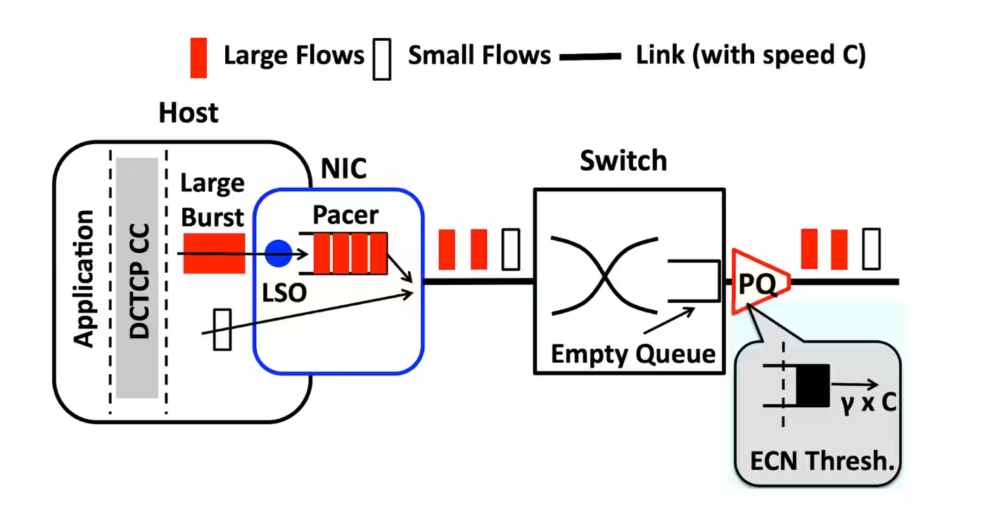
The core idea generalizes well to trading: if you want consistently low latency, you must engineer bandwidth headroom. Otherwise, a beautifully‑tuned RPC stack is trapped behind a congested link.
Engineering for both bandwidth and latency
To make “fast RPC” meaningful in production, you need a network and server design that keeps queueing rare and shallow.
Overspec links and switches where it matters
Critical paths—market‑data ingest, internal pub/sub backbones, order gateways—benefit from higher‑rate Ethernet (10/25/40/100 GbE), even when average utilization looks modest. This gives you:
- Room for microbursts without sustained queueing;
- Space for additional feeds/venues without constantly redesigning.
Switch selection and configuration also matter:
- Cut‑through switches minimize per‑hop latency but often have smaller buffers;
- Deep‑buffer switches handle big bursts better but can introduce larger queueing delays when hot.
You design topology and traffic patterns to keep these trade‑offs aligned with your risk tolerance.
Optimize server‑side data paths
Inside the server, bandwidth and latency are tightly coupled:
- Place NICs and processes in a NUMA‑aware way, so packets don’t bounce across memory controllers.
- Use multiple RX/TX queues and RSS to scale line‑rate packet handling across cores.
- For hot paths (feed handlers, gateways), consider kernel‑bypass stacks (DPDK, similar) or on‑NIC/FPGAs to reduce processing latency and increase sustainable messages per second.
A mis‑pinned process or an overloaded PCIe lane can quietly add tens or hundreds of microseconds to your apparent “RPC latency”, even if the wire‑time remains tiny.
Network design patterns for trading
Beyond raw bandwidth:
- Colocation and direct cross‑connects to venues minimize propagation delay and reduce the number of intermediate hops.
- Use IP multicast for market data fan‑out, but ensure the core and aggregation layers have enough capacity and avoid pathological fan‑in patterns that create hotspots.
- For inter‑city latency, microwave/RF links can beat fiber on propagation, but usually at lower raw bandwidth; capacity planning and traffic shaping become even more important.
- If you would rather not own and operate the hardware, a managed multi-node cluster covers the same ground as a service: two or more nodes behind a load balancer on almost any chain, with geo-distribution, autoscaling and archive nodes available — from $2,000/mo plus server cost, a one-time $200–400 setup for up to 8 nodes, and +$1,000/mo for each additional network.
A compact way to summarize some trade‑offs:
| Design choice | Pro | Con / Trade-off |
|---|---|---|
| 10/25/100 GbE uplinks | Headroom, fewer queues | Higher cost, more complex optics |
| Cut-through switches | Lower per-hop latency | Typically smaller buffers |
| Deep-buffer switches | Less loss under big bursts | Potentially higher queueing latency |
| Kernel-bypass NIC stack | Lower CPU & processing latency | More complex dev/ops, reduced OS features |
| RF/microwave inter-city links | Lower propagation than fiber | Lower bandwidth, weather sensitivity |
How to measure the real problem: Latency under load
To know whether your bandwidth and topology are actually doing their job, measure end‑to‑end latency under realistic load, not just idle‑time microbenchmarks.
Key practices:
- Track P50, P95, P99, P99.9 latency for critical paths, especially during:
- Market open/close.
- Major macro events.
- Reproduce or replay historical burst patterns rather than uniform traffic.
- Use PTP/GPS‑synchronized clocks; NTP alone is rarely accurate enough at microsecond resolution.
- Monitor:
- Link utilization per timeslice, packet drops, ECN marks, queue depth on switches.
- NIC‑level stats (overruns, drops, coalescing behavior).
Example SLOs you might define:
| Metric | Example target |
|---|---|
| Mean end-to-end latency | < 500 μs |
| P99 latency (normal load) | < 1 ms |
| P99 latency (burst periods) | < 2–3× mean |
| Packet loss on critical feeds | ~0 (no unexplained loss) |
Amdahl’s Law applies here: once queueing and throughput dominate, further micro‑optimizations of your RPC code yield diminishing returns.
Where to go deeper
For a deeper dive into the theory and practice behind this:
- Low-Latency Trading Explained: Strategy and Technology—Broad modern primer on low‑latency trading infrastructure: co‑location, microwave, FPGAs, ultra‑low‑latency switches, and network design tradeoffs for arbitrage/market‑making. Good high‑level framing to link your bandwidth discussion to concrete trading strategies.
- Give your High Frequency Trading Network the Edge | BSO—A 2025‑updated guide from a connectivity provider focused on HFT.
- Lessons from the field - Designing High-Performance Broadcast IP Networks—Engineering talk on building high‑performance multicast/broadcast IP networks.
- CloudVision® 2025: Advanced Telemetry for Scalable Network Visibility—Focused on streaming telemetry and scalable observability. Useful to extend your “how to measure the real problem” section: queue depth, drops, microbursts, and fabric health under load.
- How to Optimize and Fast Track Connectivity to Azure ExpressRoute —Hybrid/multicloud engineering talk on high‑bandwidth private connectivity and reference architectures.
- ForexVPS – Low Latency Trading—Intuitive explanation of distance, infrastructure, and latency from a retail angle.
For an RPC‑centric audience like RPC Fast, the key message is clear: you don’t just need fast RPC, you need RPC that stays fast when the network is on fire—and that only happens when bandwidth and topology are engineered as first‑class citizens.
Where that stack meets a specific chain, the entry points differ. On Solana specifically, RPC Fast runs a self-serve SaaS line — you can sign up on the free Start plan without a sales call and move up through the $45, $249 and $499/mo tiers, or take a Solana dedicated node from $2,200/mo with the server, setup and maintenance included.
We go beyond the bare RPC supply, so bring your latency concerns to us
Schedule a free infra briefing.jpg)


